

Applications
Related Products
Benefits

Features
The small footprint design combined with these lightweight and durable materials, eliminates the need for heavy lifting equipment during installation.
Fabrication facilities are strategically located in the United States and England to better serve our customers by providing cost-effective and timely logistical solutions.
Each unit includes lifting supports and stub-outs for the inlet and outlet piping to allow for quick and simple connection to the conveyance storm pipe. Traffic rated manhole frame & cover.
Inspection and maintenance activities are easily performed from the surface without the need for confined space entry or special equipment. A vacuum truck is typically used to clean the swirl chamber.

Aqua-Swirl® Certifications
- NJDEP - New Jersey Department of Environmental Protection
- California Stormwater State Water Resources Control Board - Trash Capture
- WDOE - Washington Dept. of Ecology - General Use Level Designation (GULD)

Custom & Retrofit Applications
The Aqua-Swirl® Stormwater Treatment System can be custom designed to fit a variety of field applications to include both offline and inline configurations. Retrofit applications are often suitable for Aqua-Swirl™ BYP (inline) systems when local guidelines allow its use. The angles for inlet and outlet lines can also be modified to fit most applications. With the invert of the inlet and outlet pipe at the same elevation, the Aqua-Swirl® can easily be connected directly to the existing stormwater conveyance system. Furthermore, given the modular small footprint design of the Aqua-Swirl®, the potential to disturb existing infrastructure utilities or surface features is minimized.

Easy Installation, Inspection & Maintenance
The Aqua-Swirl® has been designed and fabricated as a lightweight, durable and modular unit with no moving parts or on-site assembly requirements. The inclusion of stub-outs and lifting supports also facilitate easy installation. Since the system utilizes a single swirl chamber, inspection and maintenance activities are simplified without the need for confined space entry or the use of special equipment. Easy and open access to the swirl chamber from the surface serves to facilitate inspections and maintenance while reducing long term operational labor and equipment costs.

Proven Performance and Functionality
Independent laboratory and field testing programs confirm that the Aqua-Swirl® achieves over 85% sediment removal on a net annual basis. The 27 month field test further demonstrated its long-term functionality and retention of fine-grained clay loam textured sediment. Additional information can be provided for the NJCAT verified laboratory and field performance testing programs.

LID Designs & LEED Credits
Compatible with LID Designs
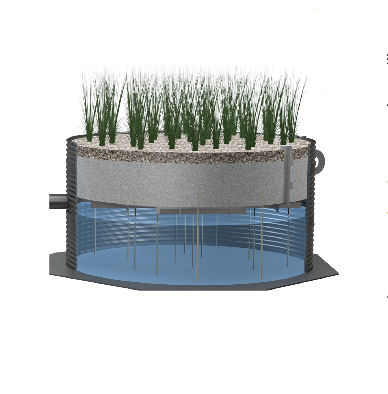
Low Impact Development (LID) design practices can be enhanced or complemented by the Aqua-Swirl™. Pretreatment for rainwater harvesting systems that use underground or above ground structures can incorporate the Aqua-Swirl™ system. It can also be used as part of a treatment train using underground infiltration structures such as the StormTank™. The small footprint device is compatible with a variety of urban LID designs. Contact AquaShield™ to learn more about including the Aqua-Swirl™ in your innovative LID design.
LEED Credits
The Aqua-Swirl® can directly contribute to gaining one (1) LEED Credits for Sustainable Sites (SS) 6.2, Stormwater Design - Quality Control. This credit is considered to meet the SS 6.2 criteria of having completed independent testing to demonstrate 80% TSS removal on a net annual basis. The Aqua-Swirl® can also help contribute to gaining several other credits within the USGCB LEED program.
Videos
AquaShield Aqua-Swirl® Hydrodynamic Separator (HDS)
Describes how the AquaShield Aqua-Swirl Bypass Model works for effective hydrodynamic separation (HDS) of total suspended solids (TSS) to improve stormwater quality.
Aqua-Swirl® Installation
Installation video of the Aqua-Swirl Hydrodynamic Separator.
Aqua-Swirl® AS-13 & AS-11 Delivery & Setup | Chattanooga, TN
Easy Transport, Simple Handling, and Quick Install of Aqua-Swirl Concentrator's AS-11 BYP and AS-13 BYP.
Operation
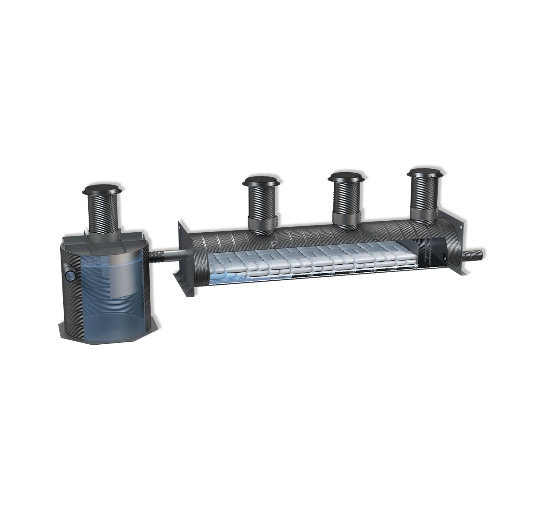
There are 3 distinct models of the Aqua-Swirl® Hydrodynamic Separator (HDS). Each HDS is designed to provide a high level of water quality treatment through the use of a single swirl chamber. Operation begins when stormwater enters the Aqua-Swirl® by means of its tangential inlet pipe thereby inducing a circular (swirl or vortex) flow pattern. The internal area of each swirl chamber represents the effective treatment area of the device where both the capture and retention of sediment, debris and free floating oil can occur. A combination of gravitational and hydrodynamic drag forces results in solids dropping out of the flow. Particles settle and migrate to the center of the swirl chamber floor where velocities are the lowest. The captured (settled) particles are retained in a cone shaped sediment pile at the base of the swirl chamber. We have outlined specific differences between the models below:
Aqua-Swirl Concentrator
The offline Aqua-Swirl® Concentrator configuration uses a separate diversion structure, or weir device located upstream of the unit. The diversion structure is designed to direct only the designed water quality treatment flow through the swirl chamber. Twin or multiple Aqua-Swirl® system configurations can be implemented to allow for higher treatment flow capabilities beyond that of a single unit.
The inline (online) configuration uses an internal bypass (BYP) design to provide full treatment for the most contaminated first flush, while the cleaner peak storm flow is diverted and channeled through the main conveyance pipe.
The BYP design can be compatible with retrofit applications. Local stormwater guidelines should be reviewed to determine whether a BYP system can be used in lieu of an offline water quality treatment unit.


Aqua-Swirl XCelerator
The Aqua-Swirl® XCelerator is a rapid or high velocity stormwater device that has no moving parts and operates on gravity flow or movement of the stormwater runoff entering the structure.
Operation begins when stormwater enters the swirl chamber by means of its tangential inlet pipe thereby inducing a circular (swirl or vortex) flow pattern. The swirl chamber diameter represents the effective treatment area of the device. Both sediment capture and sediment storage is accomplished within the single swirl chamber. A combination of gravitational and hydrodynamic drag forces results in solids dropping out of the flow and migrating to the base of the swirl chamber where velocities are the lowest.
The treated flow exits the Aqua-Swirl® XCelerator behind the arched inner baffle and through an outlet structure positioned at the effluent outlet pipe opening. The outlet structure controls the flow of treated water out of the treatment chamber and is sized to the maximum treatment flow rate (MTFR) of the system. The baffle has a high flow bypass weir which allows flows in excess of the MTFR to spill over it and continue to the outlet structure without passing through the vortex area. Thus, internal bypass flow volumes that exceed the MTFR never co-mingle with the flow volume representative of the effective treatment area.
Aqua-Swirl Trash Capture
The Aqua-Swirl® Trash Capture models is based on the same vortex-type hydrodynamic separation technology which provides for the removal of suspended sediment, trash and free-floating oil using a single cylindrical chamber for both treatment and storage of captured material. The decreasing flow rate in the swirl chamber causes suspended non-buoyant material to fall out of suspension and settle to the bottom of the chamber. The Aqua-Swirl® trash control device incorporates a 4,700 micron (μm, or 4.7 mm) perforated screen. The trash retention screen is affixed to the base of the arched baffle and extends vertically below the baffle. The base of the screen is capped horizontally and attaches to the wall of the swirl chamber to prevent trash material from escaping behind the baffle. Floatables and trash are captured and retained on the inlet (and upstream) side of the arched baffle.
A unique quality of the Aqua-Swirl® trash capture device is its modular design which allows for faster and simpler installation on new construction or retrofit projects for existing storm drainage structures. No external driving head is needed for operation other than that needed to convey stormwater flow according to the site drainage design. The invert of the inlet and outlet pipe of the Aqua-Swirl® is positioned at the same elevation so that the unit can easily be connected directly to the existing storm conveyance drainage system.

Installation

Five routine installation steps are described as follows:
Excavation and Bedding: The trench and trench bottom shall comply with ASTM D 2321, Section 6, Trench Excavation, and Section 7, Installation. The unit is installed on a stable base consisting of Class 1 stone materials per ASTM D 2321, Section 5, Materials, and compacted to 95% proctor density.
Pipe Connection Devices: Manufactured stub-outs for the inlet and outlet piping are provided to allow for simple attachment of the device to the stormwater conveyance pipe with rubber couplings. Couplings to and from the Aqua-Swirl® are supplied by the contractor. Fernco, Mission, or MarMac equal type flexible boot with stainless steel tension bands or equal are typically used. A metal sheer guard will protect the flexible connector.
Buoyancy (if required): All Aqua-Swirl® systems are supplied with an octagonal base plate extending at least six inches from the outside diameter of swirl chamber to provide additional surface area to counter any buoyant forces exerted on the device. Concrete can be poured directly onto the base plate if necessary to provide additional resistive force.
Backfill Requirements: Backfill consists of Class 1 (preferred) or Class 2 stone material per ASTM D 2321, Section 5, Materials; and, compacted to 90% proctor density. Backfill material should extend beyond the edge of the Aqua-Swirl™ to the full height of subgrade that extends laterally to undisturbed soil. Sufficient backfill should be placed over components prior to using heavy compaction or construction equipment to prevent damage. Support is provided by vertical risers to preclude vertical or lateral movements.
Traffic Loading: Reinforced concrete may need to be placed over the entire Aqua-Swirl® when subject to H-20 (or greater) traffic loading for HDPE models. AquaShield™ can assist to determine if concrete is needed. Traffic rated foundry rims and covers are installed such that no contact is made between the access riser and rebar. If traffic loading is not required, it is recommended that bollards be placed around access risers in non-traffic areas to prevent inadvertent loading by maintenance vehicles.
Maintenance
AquaShield™ recommends that periodic system inspections be performed to determine whether the disposal of captured material is needed to ensure proper operation of the Aqua-Swirl® treatment system. It is important to keep in mind that all BMPs require some degree of maintenance. Maintenance cycles are ultimately dependent on site-specific pollutant loading conditions.
Upon installation and during construction, we recommend that an Aqua-Swirl® be inspected every three months and cleaned as needed. An Inspection and Maintenance Manual is furnished for each project installation for an end user(s) to track and document system operations. A typical maintenance event for the cleaning of the swirl chamber can be accomplished with a vacuum truck. The unit should be inspected and cleaned at the end of construction regardless of whether it has reached its capacity for sediment or oil storage.
During the first year post-construction, the unit should again be inspected every three months and cleaned as needed. It is also recommended that the system be inspected and cleaned once annually regardless of whether it has reached its sediment or floatable pollutant storage capacity. For the second and subsequent years post-construction, the Aqua-Swirl® can be inspected and cleaned once annually if the system did not reach full sediment or floatable pollutant capacity in the first year post-construction. If the Aqua-Swirl® reached full sediment or floatable pollutant capacity in less than 12 months in the first year post-construction, the system should be inspected once every six months and cleaned as needed. AquaShield™ further recommends that external bypass (diversion) and convergence structures should be inspected and cleaned when feasible during inspection and maintenance events.
Essential elements of a swirl chamber inspection include observing floating materials and measuring the accumulated sediment at the base of the swirl chamber. These two activities can be performed at the ground surface and there is no need to enter the device. A typical maintenance event includes the vacuuming and disposal of floatable pollutants and sediment from the swirl chamber. Proper health and safety protocols should be followed during all inspection and maintenance events. AquaShield™ recommends that all materials removed during the maintenance process be handled and disposed in accordance with all applicable federal, state and local guidelines. Depending on the influent pollutant characteristics of the system drainage area, it may be appropriate to perform Toxicity Characteristics Leaching Procedure (TCLP) analyses on representative samples of the removed material to ensure that the handling and disposition of materials complies with applicable environmental regulations.
