

Applications
Related Products
Benefits

Features
Heavy lifting equipment is not needed for installation due to the combination of the Aqua-Filter’s modular construction and its lightweight and durable materials. Deliveries are timely and cost-effective because fabrication facilities are located throughout the United States. Aqua-Filter systems are typically installed in an offline configuration but can be designed for inline (online) installations where allowed by local regulations. Each unit includes lifting supports and stub-outs for the inlet and outlet piping to each component, allowing for quick and simple connection to the conveyance storm pipe. Inspection and maintenance activities are easily performed from the surface. A vacuum truck is typically used to perform maintenance on the swirl chamber while filter replacement requires personnel entry to the filtration chamber.

Aqua-Filter™ Certifications
- NJDEP - New Jersey Department of Environmental Protection
- WDOE - Washington Dept. of Ecology - General Use Level Designation (GULD)

Custom Applications
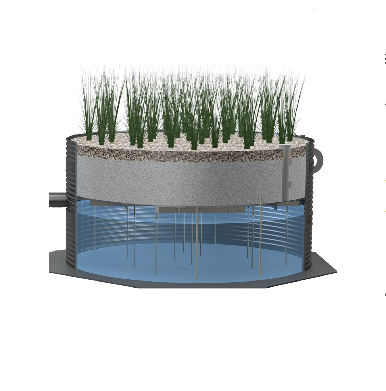
The Aqua-Filter Stormwater Filtration System can be custom designed to fit a variety of field applications to include both above- and below-grade configurations. Industrial sites also utilize the Aqua-Filter Technology for its ability to capture a variety of pollutants. Given the modular, small-footprint design of the Aqua-Filter, the system can be designed to minimize potential disturbance of existing utilities or surface features.

Easy Installation, Inspection, & Maintenance
The Aqua-Filter has been designed and fabricated as a lightweight, durable and modular unit with no moving parts or on-site assembly requirements. The inclusion of stub-outs and lifting supports also facilitate easy installation and connection for the two system components. Inspection and maintenance activities are simplified. Easy and open access to the swirl chamber and the built-in ingress/egress ladder in the filtration chamber both facilitate inspection and maintenance activities.

Proven Performance & Functionality
Independent laboratory and field testing confirms that the Aqua-Filter achieves a high level of TSS removal while maintaining a high sediment retention capacity within the filter media. A TARP Tier II field test demonstrates the ability of the Aqua-Filter to capture 90% of a clay loam textured sediment while maintaining long term performance and overall functionality.
Videos
Aqua-Filter Stormwater Filtration
Describes how the AquaShield Aqua-Filter Stormwater Filtration System works to filter out fine total suspended solids (TSS) and other contaminates of concern to improve stormwater quality.
Aqua-Filter Installation Video
Installation video of the Aqua-Filter Stormwater Filtration System.
Operation
The Aqua-Filter™ treatment train is designed to provide a high level of water quality treatment through the use of a swirl chamber (Aqua-Swirl™) for pretreatment followed by a filtration chamber for secondary treatment. The offline Aqua-Filter configuration uses a separate diversion structure, or weir device located upstream of the unit. The diversion structure is designed to direct only the designed water quality treatment flow through the Aqua-Filter system. Twin or multiple Aqua-Filter system configurations can be implemented to allow for higher treatment flow capabilities beyond that of a single unit.
The two treatment steps of the Aqua-Filter operation are described below.
Step 1. Pretreatment
Operation begins when stormwater enters the Aqua-Swirl by means of its tangential inlet pipe thereby inducing a circular (swirl or vortex) flow pattern. The swirl chamber provides pretreatment for filtration treatment by capturing and retaining coarse sediment, debris and free-floating oil. A combination of gravitational and hydrodynamic drag forces results in solids dropping out of the flow. Particles settle and migrate to the center of the swirl chamber floor where velocities are the lowest. The captured (settled) particles are retained in a cone shaped sediment pile at the base of the swirl chamber. The treated flow exits the swirl chamber behind an arched inner baffle that is positioned opposite the influent pipe and in front of the effluent pipe. The top of the baffle is sealed across the treatment channel to eliminate floatable pollutants from escaping the swirl chamber. A vent pipe is extended up the riser to expose the backside of the baffle to atmospheric conditions, thus preventing a siphon from forming at the bottom of the baffle. Water is retained within the swirl chamber between storm events to a level equal to the invert elevations of both the influent and effluent pipes.
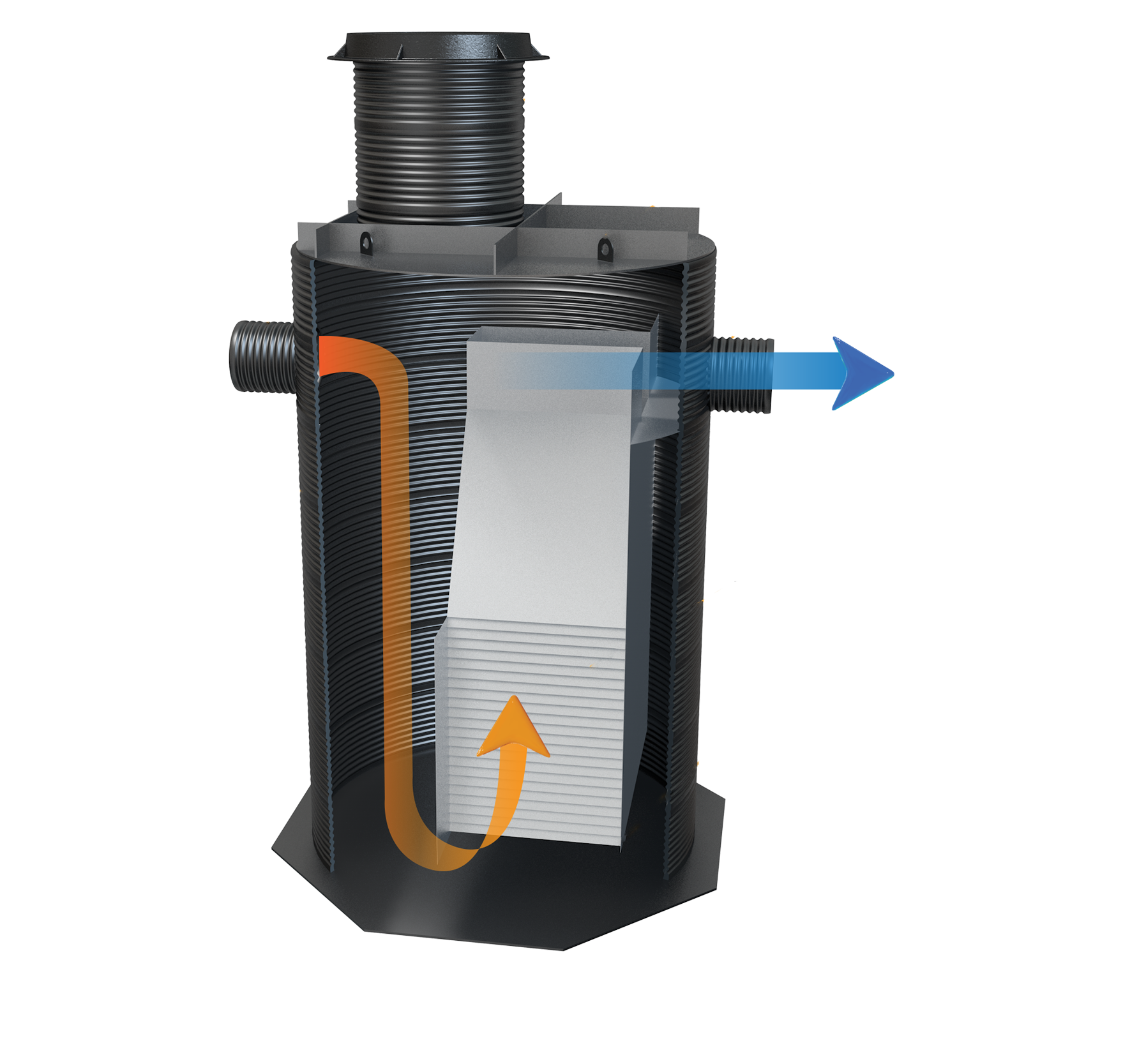
Step 2. Filtration
As pretreated water enters the filtration chamber, it is evenly distributed across the horizontal filter bed and allowed to permeate downward through the filter media under gravity flow conditions. While downflow filtration designs are most commonly used, custom upflow designs can be used where there is little vertical difference between the inlet and outlet elevations.
The filtration chamber utilizes a number of filter media rows based on the specified treatment capacity. Each filter media container measures two feet (0.6 meters) long, one foot (0.3 meters) wide, and 0.5 feet (0.15 meters) thick, providing for an area of two square feet (0.18 square meters) and a volume of one cubic foot (0.027 cubic meters). The filter containers are stacked one on top of another in an alternating configuration such that each filter row is one foot (0.3 meters) thick. Each row of filter media contains 12 filter containers and occupies an area of 12 square feet.
The filter media is capable of removing fine-grained sediment, heavy metals when bound to particulate matter and residual oil. Perlite is the most commonly used filter media in the Aqua-Filter™. Other filter media such as granular activated carbon (GAC), leaf compost, zeolite and various media blends are also available to meet site-specific discharge criteria.
Installation
Since all Aqua-Filter systems are fabricated from high-performance materials, the units are durable and lightweight and can be installed without the use of heavy lifting equipment. Lifting supports or cables are provided to allow easy off-loading and installation with a trackhoe. Compared to concrete systems, using an Aqua-Filter can significantly reduce installation costs.
Four routine underground installation steps for the Aqua-Filter are summarized below. It should be kept in mind that the Aqua-Filter can also be installed above grade to meet custom installation needs.
Excavation and Bedding. The trench and trench bottom shall comply with ASTM D 2321, Section 6, Trench Excavation, and Section 7, Installation. The unit is installed on a stable base consisting of Class 1 stone materials per ASTM D 2321, Section 5, Materials, and compacted to 95% proctor density. Additional bedding should be tamped around the “under-center” of the filtration chamber up to the springline to provide adequate support.
Pipe Connection Devices. Manufactured stub-outs for the inlet and outlet piping are provided to allow for simple attachment of the device to the stormwater conveyance pipe with rubber couplings. AquaShield furnishes the coupling between the swirl and filtration chambers. This only requires the contractor to supply rubber couplings to attach the pipes to both the swirl chamber and filtration chamber stub-outs for the system to function properly
Buoyancy (if required). All Aqua-Filter systems are supplied with anchor feet at each end of the filtration chamber to provide additional surface area to counter any buoyant forces exerted on the system. Concrete can be poured directly onto the anchors if necessary to provide additional resistive force. Note: The swirl chamber includes an octagonal base plate to counter any buoyant forces (see Step 3 of the Aqua-Swirl Installation summary).
Traffic Loading. Standard Aqua-Filter made from Polymer Coated Steel (PCS) will not require reinforced concrete. However, depending on shallow burial especially for HDPE units, a concrete pad may need to be placed over the entire Aqua-Filter when subject to H-20 (or greater) traffic loading. AquaShield can assist to determine if a concrete pad is needed. Traffic-rated foundry rims and covers are installed such that no contact is made between the access riser(s) and rebar. If traffic loading is not required, it is recommended that bollards be placed around access risers in non-traffic areas to prevent inadvertent loading by maintenance vehicles.
Maintenance
AquaShield recommends that periodic system inspections be performed to determine whether the disposal of captured material and/or filter media is needed to ensure proper operation of the Aqua-Filter treatment system. It is important to keep in mind that all BMPs require some degree of maintenance; maintenance cycles are dependent on site-specific pollutant loading conditions. AquaShield furnishes an Inspection and Maintenance Manual for each project installation for an end user(s) to track and document system operations.
Upon installation and during construction, we recommend that the Aqua-Filter system be inspected every three months and the system be cleaned as needed. During the first year post-construction, the system should again be inspected every three months and cleaned as needed. The unit should be inspected and cleaned once annually regardless of whether it has reached its sediment or floatable pollutant storage capacity. For the second and subsequent years post-construction, the Aqua-Filter can be inspected and cleaned once annually if the system did not reach full sediment or floatable pollutant capacity in the first year post-construction. If the Aqua-Filter reached full sediment or floatable pollutant capacity in less than 12 months in the first year post-construction, the system should be inspected once every six months and cleaned as needed. AquaShield™ recommends that bypass structures should be inspected whenever the Aqua-Filter is inspected and maintained as needed.
The filter media containers are the only components of the system that require replacement. The replacement of filter containers is generally needed if the filter media is observed to exhibit a dark brown or black color, and if a noticeable excessive accumulation of sediment, oil or other materials occurs across the filter bed. Filter replacement activities can be performed without the on-site assistance of an AquaShield representative.
AquaShield recommends that confined space entry techniques be used to perform tasks associated with filter replacement or entry to the filtration chamber for any other reason. A built-in ingress/egress ladder is provided in the filtration chamber and extends downward through the riser to the base of the filtration chamber and near the outlet opening. Proper health and safety protocols should be followed during all maintenance events. We also recommend that all materials removed during the maintenance process be handled and disposed of in accordance with all applicable federal, state and local guidelines. Depending on the influent pollutant characteristics of the facility drainage area, it may be appropriate to perform Toxicity Characteristics Leaching Procedure (TCLP) analyses on representative samples of the spent filter media to ensure that the handling and disposition of materials complies with applicable environmental regulations.
Essential elements of an Aqua-Filter maintenance event include the replacement and disposal of the filter media containers, as well as vacuuming of floatables, oil and sediment from the swirl and filtration chambers. Two scenarios for Aqua-Filter maintenance events are likely. The first and most common scenario provides for cleaning both components of the system by utilizing a vacuum truck and replacing the filter media containers. The second maintenance event scenario provides only for the cleaning of the swirl chamber and filtration chamber by use of a vacuum truck; but, no replacement of the filter media containers.
The filter media containers are the only components of the system that require replacement. The replacement of filter containers is generally needed if the filter media is observed to exhibit a dark brown or black color, and if a noticeable excessive accumulation of sediment, oil or other materials occurs across the filter bed. Filter replacement activities can be performed without the on-site assistance of an AquaShield representative.
