

Applications
Related Products
Benefits

Green Infrastructure Solution
The Aqua-Ponic™ Biofiltration System is a “planter” design intended to provide a green infrastructure solution to meet LID design practices. The Aqua-Ponic™ can be used to complement other underground LID practices such as water storage for rainwater harvesting, detention and infiltration. The Aqua-Ponic™ can be installed in association with raingardens, streetscapes, parking lots, or other land uses where manufactured biofiltration technology enhances stormwater management on the site.

Proven Performance and Functionality
Independent testing documents that the filter media used in the Aqua-Ponic™ achieves a high level of performance for the removal of sediment and other pollutants contained in stormwater runoff at a flow rate in excess of other manufactured biofiltration devices.

Easy Installation, Inspection & Maintenance
The Aqua-Ponic™ design uses a lightweight, durable and modular unit approach with no moving parts. An outlet stub-out allows for quick installation and connection to the stormwater conveyance system. Inspection and maintenance activities are simplified via open and direct access to the inlet, vegetation and media. Only the upper most portions of the media components typically need replacement when warranted. While full replacement of media and plants may be necessary depending on site conditions, those tasks can be completed from the surface without the need for special tools or equipment.

Aqua-Ponic™ Certifications
- NJDEP - New Jersey Department of Environmental Protection
- WDOE - Washington Dept. of Ecology - Pilot Use Level Designation (PULD)

Advantages
Most manufactured biofiltration systems fundamentally rely on a proprietary engineered soil, medium or post-plant bed flow/filter controls to achieve 80% removal of suspended sediment from stormwater runoff (commonly known as total suspended solids, (TSS)). Other pollutants such as Total Phosphorus (TP) and total (insoluble form bound to particulate matter) and/or dissolved (soluble) heavy metals such as copper and zinc. Other metals may be targeted for removal from stormwater runoff using specialized media and/or media blends. Media mixtures are commonly utilized that contain variable percentages of engineered organic or inorganic filter media, mulch, peat moss, fine- to coarse-grained sands, gravel and rip-rap. Other engineered controls such as bypass piping, drain down piping and under drains may be incorporated as a design element. The “green” aspect of these LID-based biofilters rely on the inclusion of either high-profile or low-profile vegetation (as explained below). Some proprietary biofilters can additionally incorporate aspects of infiltration to address a fundamental LID principle of runoff reduction. In essence, these manufactured biofilters are commonly utilized as a decentralized stormwater LID product as opposed to the use of larger scale public domain swale (or bioswale) or other land-based Stormwater Control Measures (SCM) specified for runoff reduction and water quality. Some urban sites are not conducive for a large scale, centralized bioswale; hence, manufactured biofilters can fill an important role within a LID-based stormwater design.
Proprietary biofilters can be classified as either a “tree box” (vault-based) or as a linear “planter.” The Aqua-Ponic™ system is classified as a planter type biofilter designed to be consistent with GI infrastructure definitions. A planter biofilter typically utilizes hardy low-profile perennial vegetation such as native grasses, shrub grasses and/or ornamental flowering plants. Planters can utilize a single type of plant or a mixture of plants can be used to enhance the view scape with a variety of vegetation. Planters can have an aspect of infiltration when site conditions allow; however, care should be taken such that the planter can sustain the vegetation during dry weather conditions. In contrast, a tree box commonly includes a higher-profile woody, moderate-size tree, shrub, or a combination of such plants but typically do not include a wide mixture of plants. A variety of plants can also be used and tailored to the climate of a given locale. A tree box can operate in the absence of vegetation when installed underground, particularly when used for decentralized infiltration should site conditions not warrant the use of plants. Whether a planter or tree box biofilter, it is important to specify plants that demonstrate viability within the climatic zone of a site installation.
Biofilters convey water downward under gravity flow conditions, often with runoff water entering the device from a curb inlet, curb cut or surface sheet flow. It is possible that a biofilter could be installed as an end-of-pipe device but the runoff flow rate and conveyance piping should be considered for the typical lower operating flow rates of these devices. Biofilters most commonly operate at a surface area loading rate ranging from 1.0 to 2.0 gallons per minute per square foot of treatment area (gpm/ft2), or infiltration rates on the order of 125 to 175 inches per hour (in/hr). These loading and infiltration rates are commensurate with public domain designs for centralized bioswales.
A unique advantage of the Aqua-Ponic™ system is its capability to provide water quality treatment at an accelerated or exponentially higher operating rate when compared to other manufactured or land based biofiltration systems. Additional information pertaining to Aqua-Ponic™ sizing can be provided on request.
Videos
Aqua-Ponic™ Installation
AquaShield's latest innovation in biofiltration, Aqua-Ponic™. This video describes the simple installation process of adding plant stabilization media, geotextile, plants, and pea gravel.
Aqua-Ponic™ Biofiltration: Green Infrastructure & Low Impact Development
The demand for Green Infrastructure is rapidly rising, and with it, the use of Biofiltration. This popular stormwater management practice offers an urban solution for site designs based on the principles of Low Impact Development, or LID, which addresses both runoff reduction and water quality treatment. Aqua-Ponic technology takes an innovative bilateral approach to meet this demand.
How the Aqua-Ponic™ Works
The Aqua-Ponic™ Biofiltration System contains a minimum 12-inch proprietary blended filter media layer which serves three operational roles by providing (1) pollutant filtration, (2) plant stabilization and (3) facilitating nutrient uptake.
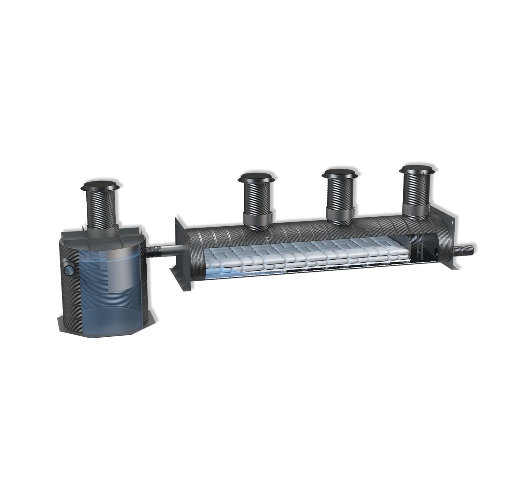
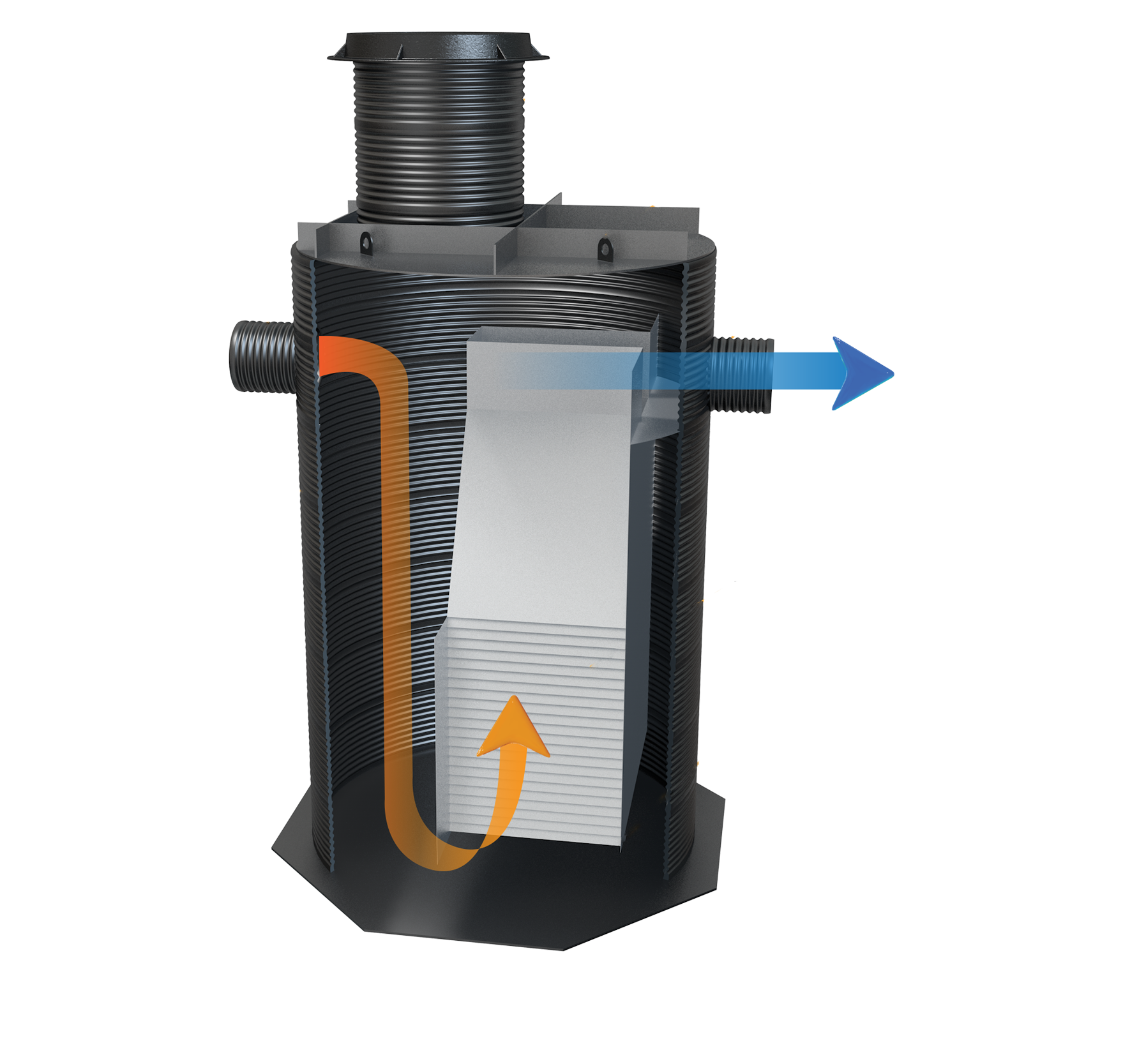
Figure 1 is an illustration of the Aqua-Ponic™ Biofiltration System. Design elements include a top layer of pea gravel underlain by the proprietary plant stabilization filter media bed. The pea gravel serves to protect the underlying plant stabilization engineered filter media bed while dispersing the influent stormwater runoff across the treatment area. Water flows downward under gravity flow conditions through the media bed and root systems of the vegetation. The filtered water then percolates further downward into the underlying water sump. The engineered filter media bed actively filters nutrients and metals during a runoff event whereby the plants will experience uptake to support plant viability. A supporting perforated steel sheet underlies the media bed. A post-filtration flow control orifice is placed across the outlet pipe opening in order to facilitate an even distribution of influent runoff across the filter treatment area. As an alternative to the top pea gravel layer, crushed recycled landscaping glass can be used which further enhances colorful view scape options for the Aqua-Ponic™.
The sump serves as a water reservoir for the vegetation during quiescent periods. A series of wicks are suspended from the base of the plant stabilization bed and extend downward to near the base of the reservoir. Water is wicked by these rods up to the engineered filter media bed which serves to provide a sustainable supply of water and any soluble nutrients and metals not trapped in the media bed during a runoff event. Treated water in excess of the sump storage volume exits the system via the outlet opening just below the base of the media bed.
Installation
Since the modular Aqua-Ponic™ is constructed of durable and lightweight Polymer Coated Steel (PCS), it can be installed without the use of heavy lifting equipment.
Four routine underground installation steps for the AquaShield™ Aqua-Ponic™ are recommended below. Site-specific conditions may necessitate deviation from these recommendations.
- Excavation and Bedding: The excavation bottom shall comply with ASTM D 2321, Section 6, Trench Excavation, and Section 7, Installation. The unit is installed on a stable base consisting of Class 1 stone materials per ASTM D 2321, Section 5, Materials; and, compacted to 95% proctor density.
- Outlet Pipe Connection Device: A manufactured stub-out for the outlet pipe is included to allow for simple attachment of the device to the stormwater conveyance pipe with a rubber coupling. This only requires the contractor to supply a rubber coupling to attach the conveyance pipe to the outlet stub-out for the system to function properly.
- Backfill Requirements: Backfill consists of Class 1 (preferred) or Class 2 stone material per ASTM D 2321, Section 5, Materials; and, compacted to 90% proctor density. Standard practices should be implemented to bring backfill material up to near surface grade to ensure structural integrity of the device.
- Activation: The unit is typically shipped without biomedia pre-installed. Inlet to the Aqua-Ponic™ biofiltration chamber should remain intact until the selected vegetation is to be planted. Also, no water should be allowed to flow through the device with the biomedia in-place until the unit is fully activated. We can suggest some plantings best suited for the Aqua-Ponic™, but it is the responsibility of the contractor to obtain the selected vegetation and appropriately plant it within the biomedia. AquaShield™ is not responsible for specifying, supplying, planting or maintaining vegetation. Once the outlet pipe connection is made and the vegetation planted, the unit is ready to receive water and can be activated. It is not necessary for AquaShield™ personnel to be on-site to activate a facility.
Maintenance
Maintenance frequency for the Aqua-Ponic™ will ultimately be determined by site-specific pollutant loading conditions. Inspections of the inlet(s), plants, top media layer and the upper portion of the proprietary media can be accomplished from the surface without special tools. AquaShield™ recommends periodic inspections following installation to determine a site-specific maintenance cycle to ensure functionality of the media and the vegetation.
We recommend that periodic system inspections be performed to determine the pollutant and trash loading characteristics. In general, quarterly inspections should be performed during the first year or operation. It is common for biofiltration technologies to undergo annual maintenance that can include media and plant replacement. It is important that a consistent maintenance program be established for the Aqua-Ponic™. AquaShield™ furnishes Inspection and Maintenance Manuals for each project installation to track and document system operations and maintenance needs.
An Aqua-Ponic™ maintenance event should first determine any obvious signs of degradation, displacement, sediment or trash accumulation, or oil in the upper layer of the unit. The top gravel layer should be completely replaced and can be removed by shoveling or vacuuming. The top three to six inches of the underlying engineered filter media may be replaced at the same time. Care should be taken not to damage the plants or disturb rootballs during media replacement. Care should also be taken when replacing a plant to avoid disturbing remaining plants. Depending on site conditions, it may be necessary to remove all the media and all the plants and completely replace these components of the system. The inlet can be manually cleaned or vacuumed through the curb inlet(s).
All inspections and maintenance activities can be performed from the surface without the need for AquaShield™ personnel to be present. We recommend that all materials removed during the maintenance process be handled and disposed in accordance with all applicable federal, state and local guidelines. Depending on the influent pollutant characteristics of the facility drainage area, it may be appropriate to perform Toxicity Characteristics Leaching Procedure (TCLP) analyses on representative samples of the spent filter media to ensure that the handling and disposition of materials complies with any applicable environmental regulations and practices.
